Transformer Oil Degassing plant CMM-6D

The CMM-6D degassing unit is designed for removal of particulate matter as well as heat and vacuum purification of electric insulating and turbine oils from water and gas.
The unit is intended for use during installation, repairs and operation of oil-filled high voltage equipment up to 1150 kV (power transformers, high voltage switches etc).
For indoor operation, ensure exhaust of removed gases into the atmosphere via piping.
Specifications
|
Parameters |
Value |
||
| 1 Processing capacity, m3/hour | |||
| – degassing, drying and filtration mode |
2-6 |
||
| – filtration and heating mode |
2-6 |
||
| 2* Processed oil parameters: | |||
| – max volumetric gas content, % |
0,5 |
||
| – max weight content of water, ppm |
5.0 |
||
| – filtration fineness, micron |
0,5 |
||
| 3 Max oil heater output temperature, ºС |
90 |
||
| 4 Max output pressure, MPa |
0.35 |
||
| 5 Oil heater power, kW |
142 |
||
| 6 Max power consumption, kW |
150 |
||
| 7 Max residual pressure in the vacuum chamber during degassing, mbar |
10 |
||
| 8 Max residual pressure in the vacuum chamber during air tightness test, mbar |
5 |
||
| 9 Max air inflow during vacuum test in 1 hour, mbar |
10 |
||
| 10 Power supply | |||
| – voltage, V |
380 |
||
| – AC 3-ph frequency, Hz |
60 |
||
| 11 Dimensions, mm max without trailer | |||
| – length |
3700 |
||
| – width |
1750 |
||
| – height |
2320 |
||
| 12 Weight, kg, max |
2250 |
||
Note – * initial oil parameters:
- olumetric gas content – below 10.5%
- mass weight content – below 0.01% (100ppm)
- temperature– above 0 ºС.
Description of the unit
The unit is a self-contained unit with all assemblies and components in the container. The container is installed on a trailer. Side walls of the container feature doors for simple access and ventilation. A compartment for tools and accessories is attached to the side wall of the unit; the compartment also contains drums with power cable and oil hoses.
The unit consists of the vacuum chamber 1, oil pump 2, metal body 3, pre-filter 4, fine filters 5, oil trap 6, oil heater 7, piping with valves, vacuum pump section and the control cabinet 8.
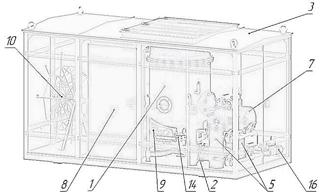 Figure 1.2 Unit general view
The vacuum pump section is an assembly of two vacuum rotary vane pumps 9. The section is connected to the vacuum chamber (1) and trap (6) via vacuum line 11 with cutoff valve 12. Pump exhausts are connected to collector 13 and lead out to the back wall of the container.
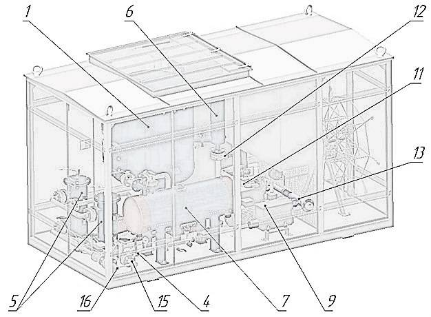
Figure 1.3 Unit general view
Tool and accessory compartment 10 is attached in the side of the container, containing cables and hoses. The vacuum chamber can be cut off from the oil pump with disk gate 14. Oil supply collector 15 and oil outlet collector 16 are located next to each other.
Parameters are controlled by: ТСМ type thermistors, thermostat, flow relay, pressure and vacuum sensors, level sensors and oil flow meter/totalizer.
Pre-filter (mesh) 4 installed at the inlet to remove particulate matter from the oil. Fineness of filtration is defined by 200 micron brass mesh installed in the case. To rinse the filter element, the filter is removed from the case and rinsed in clean transformer oil.
The oil pump 2 removes oil from the vacuum chamber. The pump is controlled from the control panel.
Fine filters 5 (figure 2) are installed for filtration of the processed oil with 1 micron fineness. For general view of the filter refer to Figure 2.
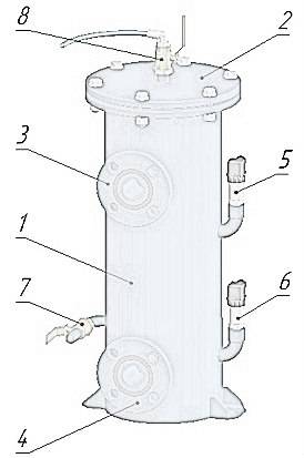
Figure 2 Fine filter: 1 – body; 2 – lid; 3 – oil inlet; 4 – clean oil outlet; 5 – pressure sensor before filter; 6 – pressure sensor after filter; 7 – contaminant drain valve; 8 – air release valve
The filter consists of lid and body supporting the filter element. The lid features a valve designed to remove air from the filter when filling with oil and to let the air in when the oil exits the filter. A tap is installed in the lower part of the body. Oil inlet and outlet are welded into the body, as well as connectors for pressure sensors to indicate pressure before and after the filter element and the pressure drop.
To replace the filter element, drain contaminants from the cartridge filter by opening the valve 7. Unscrew the bolts on the lid 2 and remove it from the filter, unscrew the hold down nut, remove filter element. Install new filter element, secure it with the hold down nut. Install the lid and secure with bolts.
The oil heater 7 (figure 3) is a cylinder with installed pipes with ceramic heating elements, inlet and outlet. For general view of the heater, refer to figure 3.
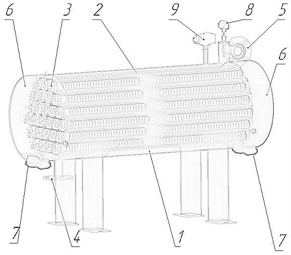
Figure 3 Oil heater: 1 – heater body; 2 – pipes for installation of heating elements; 3 – ceramic heating element; 4 – inlet; 5 – outlet
Heater operates in three equal stages. The device is managed from the control panel separately for each section. Oil temperature after the heater is controlled with the help of the temperature sensor (thermistor).
The heater is also equipped with a thermostat TS for additional control.
The body of the heater features a connector with a relief valve to prevent critical overpressure in the heater. The valve outlet is connected to the vacuum chamber.
The vacuum chamber 1 (Figure 4) is designed for removal of gas from the transformer oil. It consists of body 1, degasser lid 2, sight glass 3 for oil level monitoring. Ball valve 10 allows for air inlet. For general view of the chamber refer to figure 4.
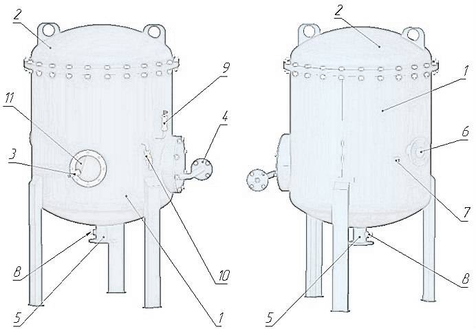
Figure 4 Vacuum chamber: 1 – body; 2 – degasser lid; 3 – sight glass and light; 4 – oil inlet; 5 – oil outlet; 6 – vacuum system connector; 7 – foam sensor; 8 – level sensor; 9 – vacuum sensor; 10 – drain valve; 11 – float stop valve
Oil trap (figure 6) is connected to the chamber to connector (6), in turn connected to the vacuum valve; the chamber includes foam sensor LS2 LS2 (7) and level indicator (8) LS1. During degassing of the transformer oil in the vacuum chamber, the residual pressure is maintained at or below 50 mbar. The oil flows into the column via piping (inlet 4) and then through the float stop valve (11) to oil collector and to oil degasser. Due to the design, the oil intensively emits gas and moisture.
Process oil exits the chamber through outlet (5) in the lower part of the body.
The oil trap 6 (figure 5) is designed to prevent oil from entering the vacuum system. For general view of the trap refer to figure 5. The trap is a metal cylinder 1 with welded connectors to the vacuum chamber 2 and to the vacuum valve 3; the device features oil indicator 4, oil presence sensor 5 and vacuum system depressurization valve 6.
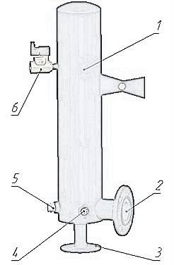
Figure 5 Oil trap: 1 – body; 2 – vacuum chamber connection; 3 – vacuum collector connection; 4 – oil indicator; 5 – oil level sensor; 6 – electromagnetic valve
Automatic control system
The automatic control system (ACS) consists of the control cabinet (CC), containing communication and control systems for the pumps, the heater and the electromagnetic valves. The front panel of the CC features a touchscreen HID, allowing the operator to control and manage the operation of the unitm as well as indicator lights for electric power and emergency stop button (Fig. 6).
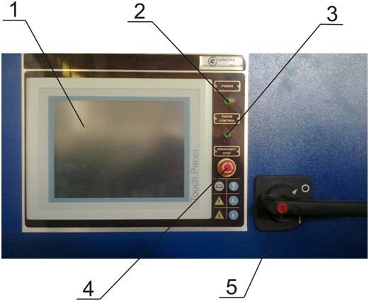
Figure 6 – Control cabinet front panel
The following elements are shown in Fig.6: 1 – touch screen (HID); 2 – power light; 3 – correct phasing light; 4 – emergency stop button; 5 – main switch handle.
The control panel contains protection and communication systems, touch screen, controllers, to which sensors are connected, and actuator controls.
Control instruments
The unit’s operation is controlled by VIPA controller and the following instruments:
- Contamination of filter elements F1, F2 and outlet pressure are shown by pressure sensors DG1 – DG4;
- vacuum is controlled by vacuum sensor DG5;
- oil level and foaming in the vacuum chamber are controlled by level sensors LS1 – LS3;
- pressure in the inlet line before the heater is controlled by pressure sensor DG6 and pressure and vacuum gauge М1;
- processing flowrate is indicated by LC flowmeter.
Heater is controlled by the following instruments:
- thermostat TS – disengages the heater when the oil temperature is above the setting;
- flow relay FS – disengages the heater when no oil flows through;
- temperature of the processed oil at the outlet of the heater is managed by the controller.
The vacuum system features two vacuum pumps designed to create the required vacuum in the vacuum chamber.
The vacuum pumps are connected to the oil trap through a valve and sylphonic compensators.
The container shelters the components and assemblies form the weather. Lifting facilities are installed on the container.
Principle of operation
The flow diagram is shown in figure 7.
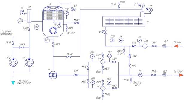 Figure 7 – Flow diagram
The unit operates in one of the following modes:
- «MANUAL MODE»;
- «HEATING FILTRATION MODE» – transfer of oil with heating and filtration;
- «DEGASING MODE»;
- «VACUUM MODE» vacuum evacuation of other equipment;
- «OUT VACUUM MODE» – simultaneous degassing and vacuum evacuation of other equipment.
Visualization and control software description
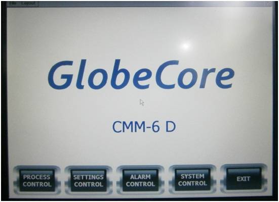
Figure 8 – Start screen of control software
- «PROCESS CONTROL» – main screen of operation visualization
- «SETTINGS CONTROL» – parameter settings screen
- «ALARM CONTROL» – fault and alarm screen
- «SYSTEM CONTROL» – devices and sensors screen
- «EXIT» – exit the visualization program (to return, press «Movicon» button).
Sample screens
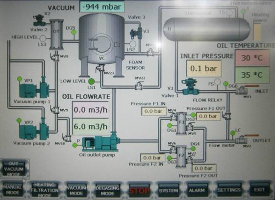
«PROCESS CONTROL» screen
The screen shows a diagram of all elements and parameters of the unit (as per the icons in the flow diagram).
The operator panel features visualization system for unit control. The program is started automatically when the control panel is powered. Figure 8 shows the start screen of the program.
WARRANTY: GlobeCore warrants the machinery supplied under this specification against defects in material and workmanship under normal use and service for a period of 12 months from date of shipment.