Bitumen emulsion plant UVB-1 (Production capacity 1 m3/hour)
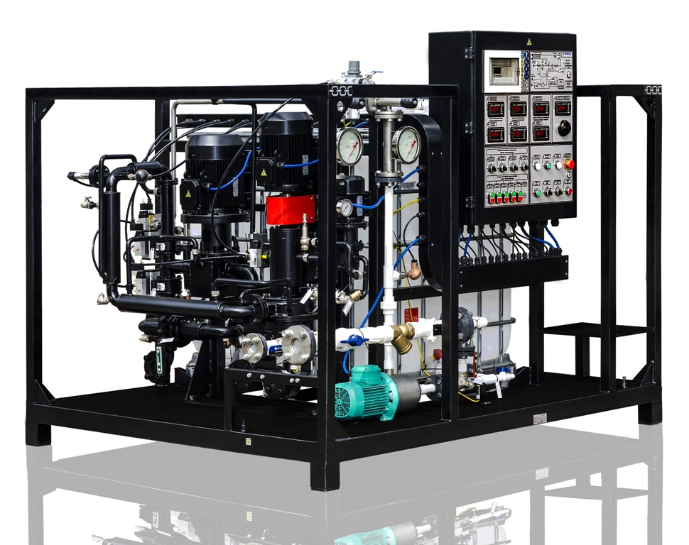
The UVB-1- bitumen unit is designed for the production of anionic and cationic bitumen emulsions, which are used in road construction for the following purposes:
- tack-coating of the old road pavement base before laying new asphalt concrete;
- preparation of cold asphalt concrete mixes;
- surface treatment of pavements;
- thin protective coatings;
- road top patching;
- dampproofing of buildings and structures;
- soft roofs construction and repairing.
The unit can be used on factories producing asphalt concrete mixes. The unit is designed for operation both indoors and outdoors, for outdoors operation use sheltered area. The unit’s operation is in compliance with placement category 4 and climatic design UHL as per State Standard 15150-69, but at ambient temperature +50С to +400С.
Basic technical specifications of the unit are given in table
Parameter | Value |
| 1 Maximum capacity (taking into account preparation time), m3/h | 1 |
| 2 Minimum bitumen consumption (at penetration rate 90…130), m3/h | 0,97 |
| 3 Water consumption, m3/h | 0,6…0,7* |
| 4 Flux consumption (at bitumen penetration rate less than), dm3/h | 0…50* |
| 5 Acid consumption, dm3/h | 1…20* |
| 6 Emulsifier consumption, dm3/h | 1…20* |
| 7 Adhesive additive consumption, dm3/h | 1…20* |
| 8 Maximum input bitumen pressure, MPa | 0,2 |
| 9 Pressure of bitumen supplied the blender, MPa | 14…16 |
| 10 Water phase pressure supplied to blender, MPa | 0,2 |
| 11 Input bitumen temperature, оС | 140-160 |
| 12 Input water temperature, оС | 40-60 |
| 13 Maximum emulsion output lift, (m) | 15 |
| 14 Maximum power consumption, kW | 17 |
| 15 Power circuit voltage at 50Hz, V | 380 |
| 16 Compressed air pressure, bar | 4…6 |
| 17 Air consumption, dm3/min | 100 |
| 18 Maximum dimensions, mm: | |
| -length | 2250 |
| -width | 1750 |
| -height | 1840 |
| 19 Maximum weight, kg | 1050 |
* Depending on the formula of produced emulsion!
DESIGN AND OPERATION PRINCIPLES
Plant UVB-1 (hereinafter init) designed for production of bitumen emulsions (see figure 1 and 2) is a semiautomatic unit, which consists of several sections mounted on a common frame and connected by means of pipelines:
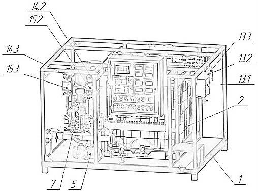
Figure 1 – Unit general view (control panel side)
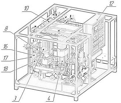
Figure 2 – Unit general view (pump side)
Item | Description | Item | Description |
1 | Frame | Valves for | |
2 | Blending tank | Water | |
3 | Pumping unit | 14.2 | Blending |
4 | Mill | 14.3 | Flux |
5 | Water pump | Flow indicator (rotameter) of | |
15.2 | Water | ||
7 | Flux pump | ||
8 | Hydrodynamic mixer | 15.3 | Flux |
9 | Blending mixer | 16 | Pneumatic bitumen three-way valve |
10 | Water phase mixer | 17 | System of heated bitumen pipelines |
12 | Control panel (CUU) | 18 | Pipelines of oil heating |
Gauging tanks section | |||
13.1 | Acid | ||
13.2 | Emulsifier | ||
13.3 | Adhesive additive |
Frame (item 1) is a space frame, which holds:
- blending tank, item 2;
- bitumen pumping unit, item 3;
- mill, item 4;
- water pump, item 5;
- blending pump, item 6;
- flux pump, item 7;
- hydrodynamic mixer, item 8;
- blending mixer, item 9;
- water-phase mixer, item 10 ;
- control panel (CUU), item 12;
- gauging tank section: item 13.1 – acid; item 13.2 – emulsifier; item 13.3 – adhesive additive;
- faucets: item 14.1 – water; item14.2 – blending; item14.3 – flux;
- flow indicators: Item 15.1 – water; item15.2 – blending; item 15.3 – flux;
- pneumatic three-way bitumen valve, item 16;
- heated pipeline system , item17;
- oil heating pipeline system, item18.
Our unit is also equipped with temperature and pressure sensors.
Temperature is gauged in points:
- water supply;
- blending supply;
- bitumen inlet;
- bitumen inlet to mixer;
- emulsion outlet.
Pressure is gauged in points:
- before unit;
- after bitumen pump;
- before mill.
Emulsifier tank heater (figure 3).
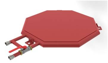
Figure 3 – Emulsifier tank heater
Heater has a flat pipe-welded design, with heat-transferring fluid circulating inside. 200 liter emulsifier tank is placed on the top of this heater.
Composite control panel (CUU) (figure 4) has a hermetical metal structure, which encloses: controller «Schneider zelio»;multifunctional measuring regulators ТРМ1-Щ2.У.Р and 2ТРМ1-Щ 2.У.РР; protective and starting equipment.
Principle electric diagram, its description and specification are presented in appendix А.
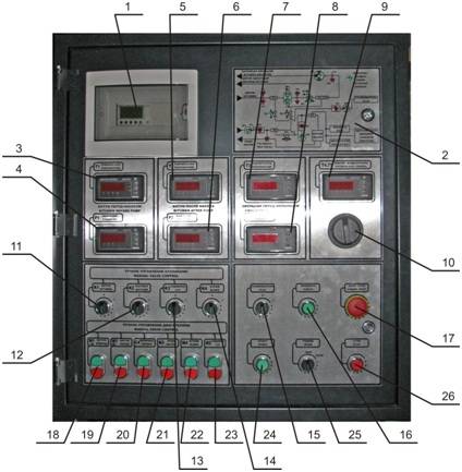
Figure 4- Composite control panel (CUU)
Item
| Description | Note | П Item | Description | Note |
| 1 | Operating controller | A11 | 16 | LED function control button «Check» | SB8 |
| 2 | Mnemocircuit | 17 | Emergency button «Emergency Stop» | SB1 | |
| 3 | Bitumen temperature gauge before pump «Т1 temperature» | A1 | 18 | Pump М1 «Bitumen forward» control button | SB2 |
| 4 | Bitumen pressure gauge before pump «Р1 pressure» | A6 | 19 | Pump М1 « Bitumen reverse » control button | SB3 |
| 5 | Bitumen temperature gauge after pump «Т2 temperature» | A2 | 20 | Mill С4 control button | SB7 |
| 6 | Bitumen pressure gauge after pump «Р2 pressure» | A8 | 21 | Pump М3 «Water» control button | SB4 |
| 7 | Emulsion temperature gauge before mill «Т3 temperature» | A3 | 22 | Pump М4 «Blending» control button | SB5 |
| 8 | Emulsion pressure gauge before mill «Р3 pressure» | A7 | 23 | Pump М5 «Flux» control button | SB6 |
| 9 | Water and blending temperature gauge «Т4, Т5 water/blending temperature» | A4 | 24 | Automatic mode «Start» control button | SB9 |
| 10 | Manual phase disconnecting switch | SD1 | 25 | Mode select switch «Mode» | SA1 |
| 11 | Valve К1 «Butumen» control switch | SA6 | 26 | Automatic mode «Stop» control button | SB10 |
| 12 | Valve К2 «Solution» control switch | SA3 | |||
| 13 | Valve К3 «Flux» control switch | SA5 | |||
| 14 | Valve К4 «Blending» control switch | SA4 | |||
| 15 | Switch for operation with kerosene (for automatic mode) «Flux» | SA2 |
Plant principle of operation is given on process layout (figure 5)
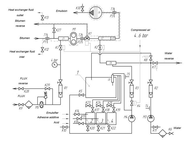
Figure 5 – Plant process layout
PROCESS LAYOUT AND EQUIPMENT REQUIREMENTS
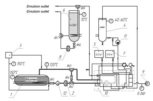
Figure 6 – Process layout of water-bitumen emulsion production: 1-bitumen boiler; 2-bitumen pump; 3- heat-transfer fluid pumping section (centrifugal pump); 4-water tank; 5-flux tank; 6-emulsion tank; 7- acid tank; 8-emulsion supply tank; 9-compressor; 10-bitumen emulsion plant UVB
Process layout of bitumen emulsion production (figure 6) consists of plant UVB-1, bitumen boiler 1, bitumen filter 12; flux tank 5, water tank 4, acid tank 7, emulsifier tank, adhesive additive tank, readymade emulsion tank 6, oil section 3, compressor 9, bitumen lines and pipelines (water, emulsion, flux, heat-transferring fluid and compressed air).
Bitumen boiler 1 is a tank with capacity up to 30 m3 equipped with heating system (any type of fuel), which can reach and keep bitumen temperature up to 160…180оС. Boiler shall be heat-insulated and equipped with gauges which control bitumen temperature and volume and also shall be equipped with bitumen pumps, bitumen valves and bitumen pipelines, which allow bitumen inlet, outlet, mixing and drainage.
Flux tank 5 with capacity 1 to 5 м3 and shall be equipped with stop valves and pressure vent valves which provide explosion-fire protection.
Water tank 4 with capacity 5 to 30 m3 equipped with heating system (any type of fuel), which can reach and keep water temperature up to 40…60оС.
Acid tank 7 is a translucent polypropylene tank with capacity 1m3 equipped with stop valves. Acid tank shall be placed on platform not lower than 1,3m.
Tanks for emulsifier and adhesive additive are standard metal drums with capacity 200 liters each, which these components are supplied in.
Readymade emulsion collection tank 6 is a vertical heat-insulated tank with capacity up to 30m3, which is equipped with heating system which keeps emulsion temperature within 40…60оС, sensors which control temperature and volume and also is equipped with pump for emulsion mixing and pumping out.
Oil section 3 is a unit for circulation and heating of thermal oil for heating of bitumen pumps, valves, bitumen pipelines and plant UVB-1. This section heats the oil up to 140…160 оС, and is equipped with control and measuring tools.
Bitumen pipelines shall have flow section not less than Du50, heating and heat-protection.
Water pipelines shall have flow section ton less than Du40.
Installed compressor shall have capacity not less than 250l/min and create pressure up 8 bar.
Plant UVB-1 is to be located either inside the manufacturing premises equipped with ventilation, or on open site under tent 6х6m.