Turbine Oil Filtration Plant CMM-4.0T

- Elimination of free and dissolved water
- Particles
- Carbon black
- Water soluble acids and alkalis
- Easy to operate and maintain
APPLICATION
CMM systems serve for inline dehydration and filtration of turbine oils for removal of free and soluble water and particulate matter.
Most frequently encountered contaminants in turbine oil are water and solids. These contaminants are detrimental to the performance and life of the oil. CMM oil purification plant are fully acceptable for removing of these contaminations.
TECHNICAL PARAMETERS
| Parameter | Value | |
| 1.Capacity, m3/h | 4 | |
| 2. Parameters of treated oil | Filtration fineness, micron | 1 … 20 |
| Humidity content, ppm | 10 | |
| 3. Vacuum pressure, bar | Vacuum pump | 0,2 |
| Vacuum vessel | 0,33 | |
| Inside the system, max | 7 | |
| 3. Specific capacity of oil heater, W/cm2 | 1,2 | |
| 4. Oil heater capacity, kW | 28,8 | |
| 5. Set power consumption, kW | 33 | |
| 6*. Power supply, V, three phase, 50 Hz | 400 | |
| 7.Outlet oil temperature, 0С | 35 | |
| 8. Dimensions, mm:- length- width- height |
1650 1150 1820 |
|
| 9. Weight, kg | 1200 | |
*Power supply parameter as per clients’ requirement
WORKING PRINCIPLE
Input pump GP1 feeds the oil via mesh filter, heater and cartridge filter FP1 into the vacuum column VC, through oil sprayer. In the vessel, the oil flows down the filling, which consists of polyplopylene rings. The rings are supported by a mesh above the bottom of the column. The flow is adjusted by input pump bypass line and can be controlled by FM flowmeter. Oil temperature is controlled by thermistor, which provides signal to the control panel CC. The oil heater FH is equipped with a flow relay interlock, which prevents operation of the heater with no oil flow. When temperature reaches maximum, the heater automatically disengages and reengages when the temperature drops below minimal. The control panel CCalso starts and stops the pumps.
The vacuum pump VP ejects the air from the upper part of the column. Air enters the column through a trottle valve TV in its lower part. When contaminated oil flows on the rings, it forms a very thin oil film with constantly changing surface. Vacuum lowers partial pressure of water in the oil and the water in free or emulsified state quickly evaporates. The moisture is separated in the moisture separator filter FS. Purified oil accumulates at the bottom of the vessel and is sucked out through the cartridge filter FP2 by the output pump GP2.
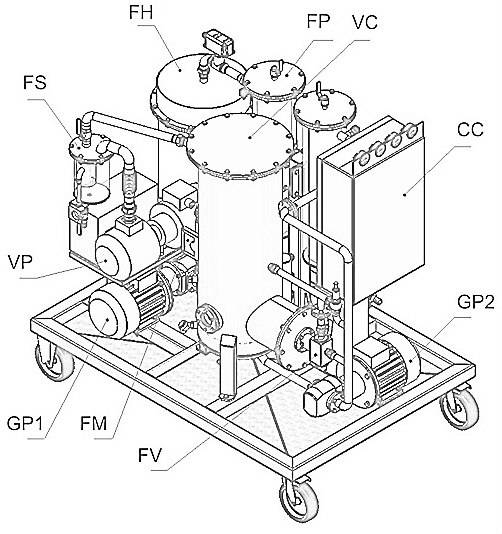
GP1 – oil inlet pump; VC – vacuum chamber; FM – flow meter; CC– control cabinet; FH – oil heater; VP – vacuum pump; GP2 – oil outlet pump; FP – filters; FS – moisture separator; FV – float valve.
The vacuum chamber VC is a cylindrical container, filled with polypropylene rings, which. Oil level sensors are installed at the bottom of this chamber. Inside mounted float valve provides the stable oil level in the chamber.
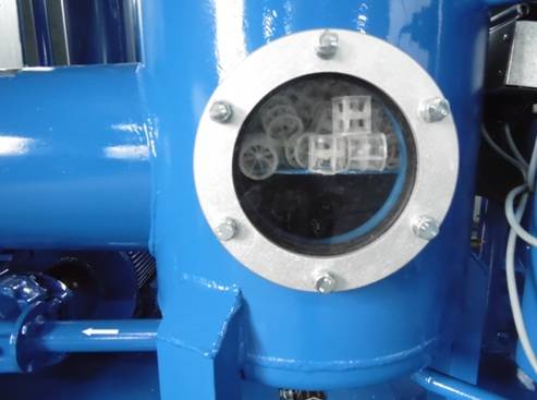
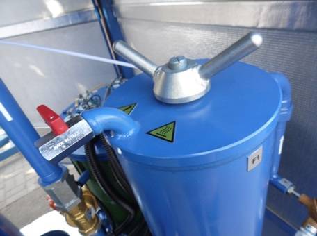
The coarse FP and fine FP filters are designed for the filtration of treated oil. Filtration fineness – 5 mkm. In the filter consists of filtration elements and a block of magnets. Cleaning of magnets is done during the replacing of filter elements. There is a valve, installed on the cover of the filter, which is designed for air outlet while filling the oil filter and air inlet when draining the oil out of the filter. The drain valve is mounted at the bottom of the filter.
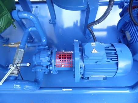
The inlet GP1 and the outlet GP2 pumps – are gear pumps NSH-50. An asynchronous three-phase motor with short-circuited rotor drives the pump (capacity 3 kW, rotating speed – 1500 / min). This pump is equipped with a bypass line with a tap.
The vacuum pump VP СР 40-620 creates the vacuum in the VC vacuum chamber. An asynchronous three-phase motor with short-circuited rotor drives the pump (capacity 3 kW).
Vacuum trap FC is a cylindrical container with a transparent display tube to control its filling. There is also installed a level sensor, which switches off the pump, in case of filling the trap. It is a necessary measure to prevent the oil from falling to vacuum pump.
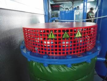
The oil heater FH is a cylindrical thermally insulated container, which is equipped with electric heaters (24 TENs of capacity 1,2 kW). The oil output temperature is monitored with thermo-resistor signal, which can be viewed on the control panel. If the oil temperature reaches its maximum or minimum, the oil heater will be accordingly switched on/off. The performance of the oil heater is possible only in case, when oil flow sensor shows, that the pipelines are not empty.
The control of electrical components is done on the shield of control panel, in which is installed switching, controlling and measuring equipment. Location and description of control elements is shown on the picture.
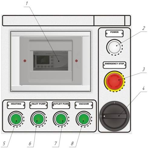
1 – controller Alpha 2; 2 – signal lamp, which lights, when the unit is supplied with electricity; 3 – emergency stop; 4 – electrical switcher; 5 – the oil heater «start/stop» button; 6 – the oil inlet pump «start/stop» button; 7 – the oil outlet pump «start/stop» button; 8 – the vacuum pump «start/stop» button.