Transformer Oil Purification Plant CMM-1.0
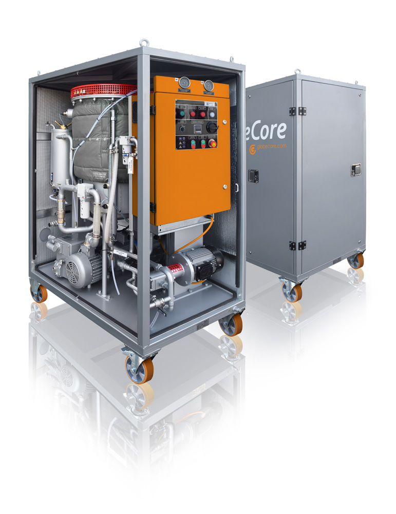
The mobile oil station CMM-1,0 (hereinafter referred to as plant, unit, station) is designed for removal of solids and water from electric insulation oils, with viscosity not exceeding 70 cSt at 50 °С.
The station can purify oil to purity class 9, starting from purity class 13 (mass content of contaminants no more than 0.004%) if the substance purified repeatedly passes through filtration block.
The plant is used during mounting, maintenance and operation of oil-filled high voltage equipment (power transformers, high-voltage switchgears, etc.).
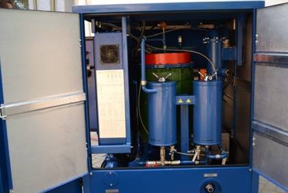
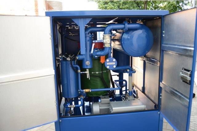
The station is a frame structure with closing doors. Its components: vacuum column 1, composite control unit CCU 2, oil pumps 3 and 4, vacuum pump 5, prefilter, coarse cartridge filter 6, 7 and fine cartridge filter 8, pipeline system 11 with gate and control valves are installed on the frame.
The general view of the station is shown in figure 1.
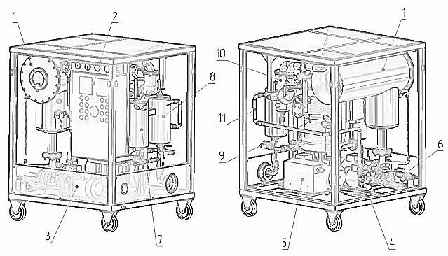
Figure 1 – CMM-1 general view (doors are not shown for convenience)
TECHNICAL DATA
|
№ |
Parameter |
Value |
| 1 | Maximum capacity, m3/h:
– drying and filtration mode – filtration mode |
1,0 1,0 |
| 2 | Maximum oil output temperature in heating mode, °С |
60 |
| 3* | Treated oil parameters (at initial moisture content of no more than 50g/t):
– maximum moisture content by weight , gram per ton – filtration fineness, mcm |
10,0 5 |
| 4 | Oil feeding height relative to outlet fitting, m |
20 |
| 5 | Input pressure, MPa, no less than |
0,1 |
| 6 | Oil heater power, kW, |
25,2 |
| 7 | Oil heater mean surface power, kW/cm2, no more than |
1,1 |
| 8 | Rated power consumption, kW |
29,7 |
| 9 | Three-phase VAG @ 50 Hz, V |
380 |
| 10 | Maximum dimensions, mm
– length – width – height |
1240 1250 1650 |
| 11 | Maximum weight, kg |
750 |
Note * With initial oil parameters as follows:
- moisture content by weight – no more than 0,005% (50g/t)
- oil heating temperature up to +60±5 ºС within 30 minutes of heating;
- gas content – no more than 10%
Mesh filter MF 6 is installed at the input of the unit to remove mechanical impurities from the oil. Filtration rating of the filter is defined by 200 micron brass mesh, fixed in the casing. For filter element washing, it is necessary to take the filter from the input manifold and wash it in the clean transformer oil.
Pumps Р1 and Р2 – installed for input and output of transformer oil. Pumps are controlled from the composite control unit. The pumps are equipped with by-pass line and valves V7, V8.
Cartridge filters F1, F2 (figure 6) are designed for filtration of the treating oil. Filtration fineness is 5 mcm. General view of the filter is given in figure 2.
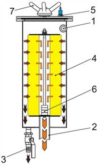
Figure 2 – Cartridge filter: 1 – oil input line; 2 – filtered oil output line; 3 – contaminant drain valve; 4 – filter element; 5 – air vent plug; 6 – magnets; 7 – clamp
It consists of a cover and a case, where filter elements of EFMG type are installed. The cover is equipped with a plug for air outlet, when the filter is filled with oil and for air inlet in case of oil draining of the filter. In the bottom of the filter it is designed a manifold with a valve. Oil input and output lines are welded to the case.
Vacuum column CV (figure 6) is designed for heating and drying of transformer oil. General view of the vacuum column is shown in figure 3.
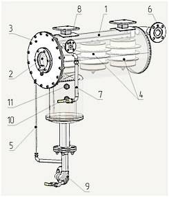
Figure 3 – Vacuum column: 1 –body; 2 – viewing window; 3 –cover; 4 –filter-activator (sprinkler);
5 –indicator of level; 6 – pipe connecting to a vacuum system; 7– inlet air pipe; 8 – oil inlet pipe; 9 – oil outlet for processed oil; 10 –lower level sensor; 11 –top level sensor
OIL HEATER
Oil heater is a thermally insulated cylindrical container with electric heaters inside (12 pieces electric heaters with power of 1.2 kW). To prevent overheating, there is a sensor for measuring and regulation of temperature on outlet of the heater.
CONTROL BOX
The control cabinet is designed for placement of the electric equipment required for regulation of the unit operation. It is a metal cabinet with lockable door. The inner panel contains electrical switching equipment. The panel contains control buttons and light indication devices.
Figure 4 shows general view of control cabinet front panel, which contains:
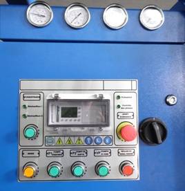
Figure 4 General view of control cabinet panel
Control and measurement devices
The unit operation is controlled via the following control and measurement devices:
- measuring regulator shows treating oil temperature at the output of oil heating block of vacuum column;
- pressure gauges M1-M2 show contamination of filter elements in cartridge filters F1 and F2;
- vacuum gauge В is used for control of vacuum value;
- light indication on the CCU front panel shows whether heating elements TEH are switched on/off.
Flow diagram is shown in Figure 6.
 Figure 6- CMM-1,0 Flow diagram: К1, К4, К7, К13 – valves DN20; К2, К3, К5, К6, К9, К10, К11, К12, К14 – valves DN 15; К8 – valve DN50; К16 – three way ball valve DN20; L1 – L3 – level sensors; R1 – moisture separator; ТP – sensor for regulator-meter temperature;; ТS – thermostat; SP – flow switch;VM – vacuum meter; М1 – М3 – manometers; CL1 – inlet oil fitting; CL2 –outlet oil fiiting; PF– mesh filter; КО1 – КО3 – check valve; FV – dehumidifier; КS –safe valve; F1, F2 –cartridge filters.
The CMM unit can be operated in the following modes:
- Filtration;
- Filtration with pre-heating and thermo-vacuum purification.
GlobeCore OIL PURIFICATION PLANT TYPE CMM-1.0