Transformer Oil Purification Plant CMM-2.2
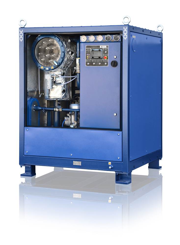
Transformer oil purification plant CMM-2,2 is designed for removal of solids and thermo-vacuum purification from water and gases of lubricant and electric insulation oil with viscosity of no more than 70 cSt at 50C.
The unit may be used for heating of oil filled electric equipment with hot transformer oil, vacuum drying of transformers and evacuation or transformers. The unit is designed for installation, repair and operation organizations which process transformer oil.
The unit is not designed for operation in explosion hazard areas, as well as in toxic or chemically aggressive environments.
When using the unit indoors, ensure safe exhaust of gases into the atmosphere by pipelines.
Technical specifications
Parameter | Value | |
| 1 Minimum capacity, l/h | ||
| – thermo-vacuum drying and filtration mode | 2200 | |
| – filtration and heating mode | 2200 | |
| 2* Processed oil parameters: | ||
| – total max has content, % | 1,5 | |
| – max moisture content, g/ton | 10 | |
| 3 Max oil temperature at unit output, ºC | 85 | |
| 4 Output pressure, MPa | 0.2 | |
| 5 Oil heater max power, kW | 53 | |
| 6 Max power consumption, kW | 60 | |
| 7 Electric power supply | ||
| – voltage, V | 400 | |
| – frequency, Hz | 50 | |
| 8 Dimensions, mm | ||
| – length | 1530 | |
| – width | 1010 | |
| – height | 1910 | |
| 9. Max weight, kg | 720 | |
Note – * with initial oil parameters:
- gas content by volume – below 10.5%
- moisture mass content – below 0.005% (50 g/tonn)
- temperature – above 0ºC.
The unit is a container with all components and assemblies inside. The side walls of the container feature hatches for access and servicing.
The unit consists of the following components: vacuum chamber 1, input pump 2, heater 5, output pump 3, fine and coarse filter cartridges 6, control cabinet 8, pipelines and valves. Process parameters are managed by Mitsubishi α2 controller base on: TCM type temperature sensor, ТС-2 thermostat, flow relay, Suco vacuum relay, ЕС 3016 РРАSL level sensors, VP02E foaming sensor, М1, М2, М3 manometers for visual control of pressure on filters and vacuum meter VM for control of vacuum in the vacuum chamber.
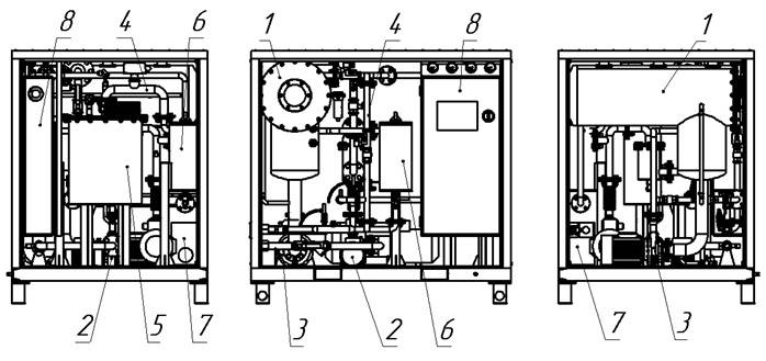
1 – vacuum chamber; 2 – input pump; 3 – output pump; 4 – pipelines; 5 – oil heater; 6 – fine filter; 7 – vacuum pump СР 30-620; 8 – control panel
Mesh filter
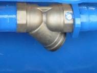
A mesh filter at the unit’s inlet removes solid particles from the oil. Fineness of filtration is defined by the 200 micron brass mesh secured in the filter’s case. To rinse the filter element, remove it from the inlet and rinse in clean transformer oil.
Oil pumps
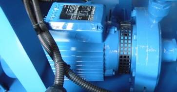
The pumps Calpeda type NM 2 and 3 input and output oil to and from the unit respectively. The pumps are controlled from the control panel.
Fine and coarse cartridge filters
Fine and coarse cartridge filters remove solids from processed oil. Filtration fineness are 5 and 25 micron respectively.
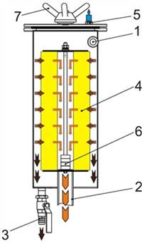
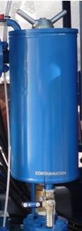
1 – oil inlet; 2 – filtered oil outlet; 3 – contaminant drain valve; 4 – filtering element; 5 – air release valve; 6 – magnets; 7 – hold down screw
The device consists of lid and frame, which supports FE-16, FE-28 type filtering element. The lid is equipped with a valve which allows to release air from the filter when it is filled with oil and to let air in when the oil is drained form the filter. Oil inlet and outlet are welded to the case. The replace filtering elements (cartridges), drain contaminants from the filter by opening the valve 3. Turn the handle 7 of the pressing screw several turns counter-clockwise, turn the lid’s stock in the same direction against stop, then remove the lid from the filter, unscrew the hold down nut and remove filtering element. Install the new cartridge, secure it with the hold down nut. Install the lid back on to the filter by repeating the steps above in reverse order.
Oil heater
The heater is a vessel with a total of 53 kW heating element. The heater is equipped with input and output lines and a drain valve. Refer to Figure 4.4 for general view of the heater. The heater is controlled from the control panel.
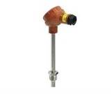
Oil temperature is controlled by the temperature controller, which receives signals from thermistor TP, and thermostat TS (see Fig. 4.7)
An interlock flow relay prevents heater operation with no oil flow to protect the heater from damage.
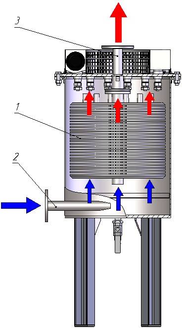
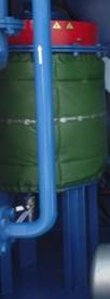
1 – heating section; 2 – cold oil inlet; 3 – hot oil outle
Vacuum chamber
The vacuum chamber 1 is designed for thermal vacuum drying of transformer oil. Ball valve K3 is attached to the column for connection to the vacuum system, as well as vacuum meter VM, level sensors L1 – L2, a visual oil level control indicator and foam sensor OS. The oil enters the column through the inlet, then flows to the activator filter and the outlet.
The design of the sprayer facilitates intensive emission of gas and water from the oil during processing.
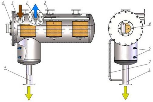
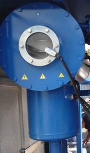
1 – inlet; 2 – vacuum system connection; 3 – activator filter (sprayer); 4 – processed oil outlet; 5 – level sensors; 6 – sight glass7 – visual level indicator
Vacuum pump
The vacuum pump VP is installed to create the necessary vacuum in the system. The vacuum pump is connected to the vacuum chamber CV by pipelines.
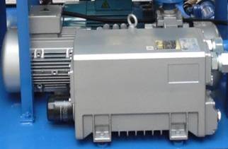
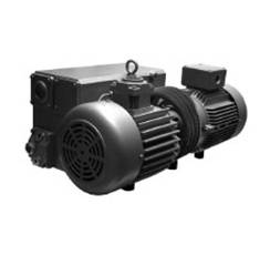
Vacuum pump type СР 30-620
Vacuum trap
Vacuum trap R is designed to prevent oil from entering the vacuum system. It has a ball valve (K14) for oil drain.
Control cabinet
The control cabinet contains electric components required for unit operation. The cabinet features lockable doors. The panel inside contains control and communication circuits. The cabinet is equipped with control buttons and lights.
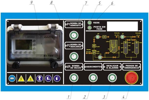
| Pos | Name/Purpose | Designation in the electric diagram |
| 1 | Controller Mitsubishi α2 | U4 |
| 2 | Heating mode select button | S6 |
| 3 | Operation mode select button | S7 |
| 4 | P1 pump start/stop button | S2 |
| 5 | P2 pump start/stop button | S3 |
| 6 | VP vacuum pump start/stop button | S4 |
| 7 | Sound signal acknowledge and alarm reset button | S5 |
| 8 | Emergency stop button | S1 |
| 9 | Correct connection indication | LD4 |
| 10 | Power supply indication | LD3 |
Instruments
The unit is controlled by the Mitsubishi α2 controller with the help of the following instruments:
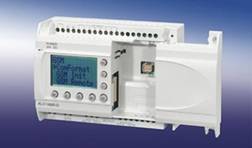
- contamination of filtering elements in cartridge filters F1, F2 and unit output pressure can be monitored on manometers М1-М3;
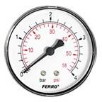
- vacuum is controlled by vacuum meter VM and vacuum relay;
- oil level control in the vacuum column is controlled by level sensors and foam senso;

Oil heater is controlled by the following systems:
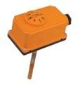
- thermostat disengages oil heater when oil temperature exceeds preset maximum;
- the flow relay disengages oil heater when no oil is flowing through the heater;

- temperature controller manages processed oil temperature at the output of the heater
Flow diagram
 СV – vacuum chamber; P1 – P2 – pumps; K1 ÷ K16 – ball valves; SV1 ÷ SV3 – electromagnetic valves; MN – oil heater; ВV1 ÷ ВV4– check valve; F1, F2 – cartridge filters; М1, М2, М3– manometers; VМ – vacuum meter; РП – flow relay, ТP – temperature controller sensor; TS – thermostat; L1 ÷ L2– level sensors; OS – foam sensor; VP – vacuum pump; РF – mesh filter; RV – vacuum relay; FV – moisture separator; R – trap; CL1 – oil inlet; CL2 – oil outlet.
The unit can be used in the following modes:
- “Heating and filtration” (H&F);
- “Thermovacuum oil drying” (Dry);
- “Vacuum evacuation of equipment” (Vac);
In the heating and filtration mode the pump P1 pumps the oil through the input valve К1 and pre-filter PF, check valve ВV1, heater MN, filter F1, electric valve SV2, check valve ВV3, valve К2 and to the outlet of the unit.
In this mode the oil is filtered and heated.
In this mode of operation, the heater and the input pump P1 are controllable. Output pump P2 controls are locked out.
The transformer oil is degassed by application of vacuum and heat.
In this mode the pump P1 pumps the oil from the unit’s inlet to valve K1, pre-filter PF, check valve BV1, oil heater MN, filter F1, electric valve SV1 to the vacuum chamber CV. Hot oil (50…60ºС) free from solids passes in the chamber through activator filter (sprayer). The vacuum in the chamber is maintained by vacuum pump VP. Vacuum is adjusted by valve K7 and is controlled by vacuum meter VM.
The moist air then passes through valve K3 and the trap and is exhausted to the atmosphere by the vacuum pump VP.
The oil from the chamber is pumped by the pump P2 through cartridge filter F2, check valve BV2 and ball valve K2 to the unit’s outlet. The vacuum in the chamber is maintained by the vacuum pump VP at -0.8 bar.
When the oil passes through the chamber, vacuum extracts moisture and air dissolved in the oil.
In this mode, oil is filtered, dried and degassed.
A warm up and adjustment mode is facilitated to prevent bad quality oil output in the initial moments of operation. In the adjustment mode, the vacuum chamber is filled with oil, after which the unit is warmed up, the oil circulating through:
- vacuum chamber СV;
- oil pump P2;
- cartridge filter F2, check valve ВV2;
- ball valve K4 and check valve ВV4, valve K2 closed;
- oil heater MN;
- cartridge filter F1 and electric valve SV1.
During circulation, the output pump may stop when oil level drops below the lower level sensor To avoid that, fill the chamber with oil to the level above the lower level sensor.
In this mode, all actuators can be controlled.
Vacuum equipment evacuation» mode (Vac).
In this mode the unit evacuates air from third party equipment with the vacuum pump VP.
In this mode, the VP pump may be controlled. Pumps P1, P2 and the oil heater are locked out.
WARRANTY
GlobeCore warrants the machinery supplied under this specification against defects in material and workmanship under normal use and service for a period of 12 months from date of shipment.
