Foam bitumen unit UVB-L
The bitumen unit UVB-L is designed for obtaining foam bitumen samples.
The unit can be operated by organizations, producing asphalt concrete mixtures, as well as road construction and repair organizations.
The unit is designed for indoor operation.
The design of the unit ensures normal operation in ambient temperatures from +5 0С to +40 0С and relative humidity 70%.
Specifications
|
Item No |
Parameter |
Value |
| 1. | Min capacity of the mixer, bitumen, l/hour |
600 |
| 2 | Water consumption, l/hour: min
max |
6 30 |
| 3 | Air consumption, l/hour: min
max |
0 100 |
| 4 | Bitumen pressure, max, bar |
16 |
| 5 | Water pressure, max, bar |
6 |
| 6 | Air pressure (to mixer) max, bar |
6 |
| 7 | Air pressure (to controls)
min, bar max, bar |
4 6,3 |
| 8 | Bitumen temperature, 0С min
max |
140 160 |
| 9 | Water temperature, 0С min
max |
20 60 |
| 10 | Oil temperature (for heating), 0С min
max |
120 180 |
| 11 | Rated power, kW,
Bitumen pump Oil pump Heaters Control Total |
3 2,2 5,1 0,1 10,4 |
| 12 | Power supply voltage at 60 Hz V, |
440 |
| 13 | Bitumen tank volume, l |
20 |
| 14 | Water tank volume, l |
20 |
| 15 | Heating oil volume, l |
10…15 |
| 16 | Dimensions, mm,
length width height |
1250 970 1490 |
| 17 | Weight, max, kg |
400 |
Scope of supply
|
Item No |
Name |
Amount |
| 1 | Foam bitumen UVB-L unit |
1 |
| 2 | Documentation | |
| – manual and certificate on UVB-L |
1 |
|
| – manual and certificates on components |
1 set |
|
| 3 | Spare parts as per packing list | |
| – water heater ТЕН 135Б 8,5/1,5П 240 |
2 |
|
| – oil heater ТЕН 100А 13/1,2 |
3 |
|
| – pressure transducer А-10 assembled (capillary, membrane) |
1 |
|
| – thermistor ТСМ -1-3-50М |
3 |
|
| – neon lamp |
5 |
|
| – button B130 DY |
1 |
|
| – button B132 K20KY |
2 |
|
| – switch B130 SL20Y |
1 |
|
| – electromagnetic relay MY2-24VDC bar included |
1 |
|
| – electromagnetic relay MY3-220VDC bar include |
1 |
|
| – six side wrench 5 |
1 |
|
| – bucket 20 l |
2 |
|
| – pipe TRN 10×8 |
5 м |
|
| – plastic funnel Æ12 |
1 |
|
Scope of application and description of the unit
The bitumen unit UVB-L is designed for obtaining foam bitumen samples.
The unit can be operated by organizations, producing asphalt concrete mixtures, as well as road construction and repair organizations.
The unit is designed for indoor operation.
The design of the unit ensures normal operation in ambient temperatures from +5 0С to +40 0С and relative humidity 70%.
The unit is designed as a frame, supporting various components and assemblies, interconnected by piping.
Unit design
See figures 1, 2, 3, 4 and 5 for general views of the unit. See table 3 for a list of components
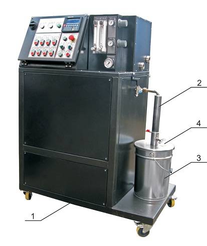
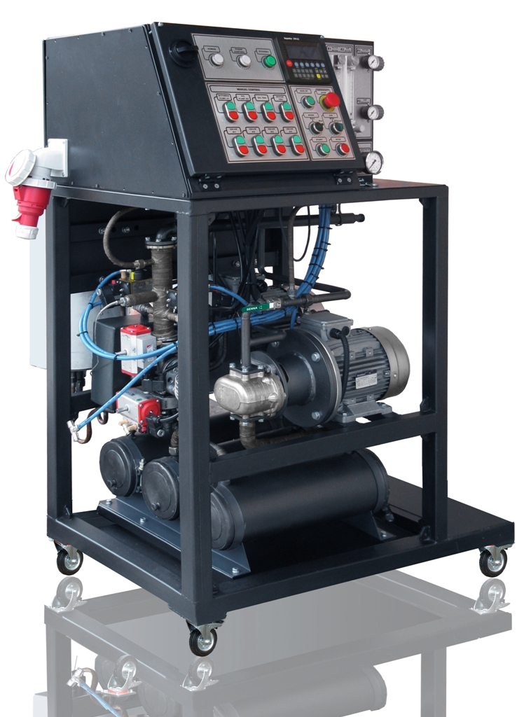
Figure 1 – General view of the unit
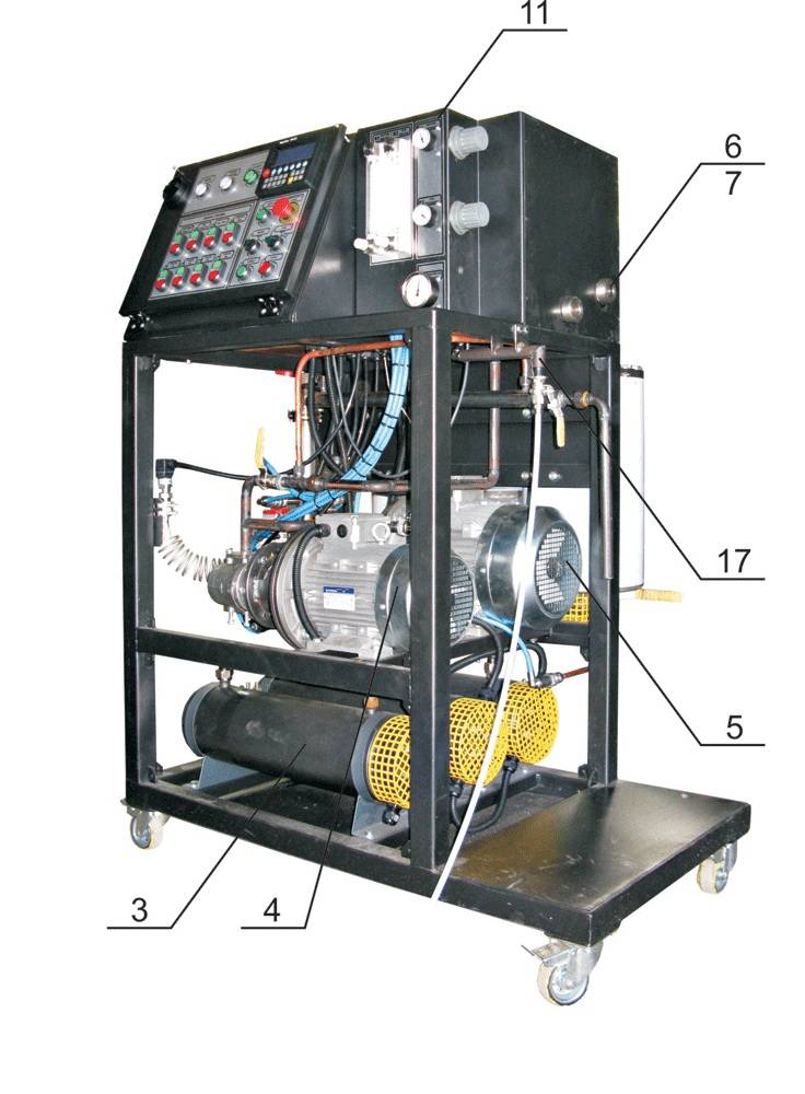
Figure 2 – General view of the unit
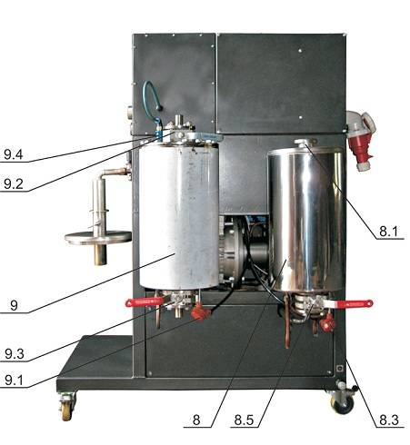
Figure 3 – General view of the unit
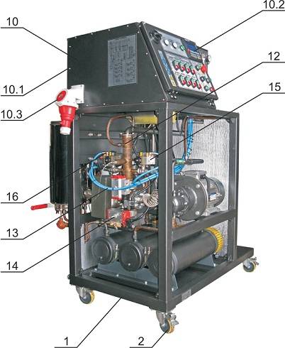
Figure 4 – General view of the unit
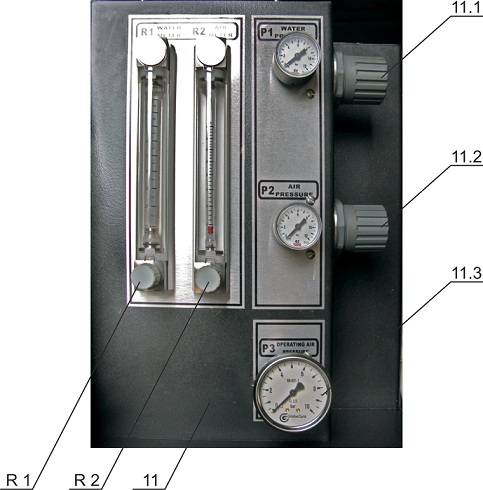
Figure 5 – Partial view of the operating panel
| No | Item | Quantity |
| 1
2 3 4 5 6 7 8 8.1 8.2 8.3 8.4 8.5 9 9.1 9.2 9.3 9.4 9.5 10 10.1 10.2 10.3 11 R1 R2 11.1 11.2 11.3 12 13 14 15 16 17 |
Frame
Wheel Oil heater Oil pump Bitumen pump Extension tank Breather valve Bitumen vessel Cover Copper heat exchanger Temperature sensor Circulation pipe Drain valve Water vessel Temperature sensor Water input valve Water drain valve Sliding valve for air input Water input pipe Electric control cabinet Extendable panel Tilt panel Input socket Pneumatic panel Water input flowmeter with adjustment valve Air input flowmeter with adjustment valve Water input pressure regulator Air input pressure regulator Collector Mixer Bitumen input valve К1 Return bitumen valve К2 Water valve К3 Air valve К4 Input pneumatic valve |
1 4 3 1 1 1 1 1 1 1 1 1 1 1 1 1 1 1 1 1 1 1 1 1 1 1 1 1 1 1 1 1 1 1 1 |
The unit consists of a frame 1 installed on four wheels 2.
The frame 1 supports: three-section oil heater 3, oil pump 4, bitumen pump 5, expansion tank 7 with breather valve (not displayed), bitumen tank 8, water tank 9, control cabinet 10, pneumatic panel 11.
Mixer 12 and pneumatic control valves are attached to the bitumen pump 5:
- К1 bitumen in – 13
- К2 bitumen return – 14
- К3 water in – 15
- К4 air in – 16
The frame 1 is a frame with threaded mounts for thermal and noise insulation panels.
Four turn wheels 2 allow for easy movement and placement of the unit
Three section heater 3 is a stream system with three sections with a TEH-1,2 tubular heater installed at each section. All sections are thermally insulated.
Oil pump 4 is a gear pump with motor P2 at 1.5 kW.
Bitumen pump 5 is a P1 motor gear pump at 3 kW. The gear pump is equipped with oil jacket for pre-heating the pump prior to start.
Expansion tank 6 is a 5 liter tank with breather valve 7.
Bitumen tank 8 is a thermally insulated tank with cover 8.1. The tank is equipped with copper heat exchanger for bitumen heating 8.2, temperature sensor (T1) 8.3, circulation pipe with spreader 8.4 and drain valve dy 32.
The water tank 9 is a 20 liter thermally insulated air tight vessel. The vessel is equipped with a spiral ТЕН-1.5 heater, temperature sensor 9.1, water input valve 9.2, water drain valve 9.3, slide valve 9.4 for compressed air input and water input pipe 9.5.
The control cabinet 10 is an air tight metal structure with extendable panel 10.1 and tilt panel 10.2. The extendable panel contains the power equipment, and the tilt panel contains the controller and control buttons. An input plug 10.3 for power connection is installed in the side of the control cabinet.
Pnematic panel 11 is equipped with water input flowmeter R1 and air flowmeter R2. The panel also contains Compressed air pressure regulator (МС1) – water input 11.1 with pressure gauge, compressed air pressure regulator (МС2) – air input 11.2 with pressure gauge and air distribution collector 11.3 with pressure gauge.
Mixer 12 (see Figure 2) is an injection mixer with a 3.5 mm nozzle, with an insulated oil jacket. Pneumatic control valves are installed on the mixer:
- К1 – bitumen in 13
- К2 – return bitumen 14
- К3 – water in 15
- К4 – air in 16
Pumps, tanks, heater and mixer are connected by pipes with thermal insulation shielding. Pneumatic system (see Figure 4) is connected by a blue pneumatic conduit with an input pneumatic valve 1 (figure 4).
The heating oil circulation system includes: connection pipelines, oil circulation pump, expansion tank and oil input valve.
Principle of operation
Before start, the operator connects the unit to power supply 10.3 and compressed air supply 17, fills bitumen tank 8 with bitumen and water tank 9 with water.
After start, the unit warms up.
Oil pump 4 pumps the oil through oil heater 3, then through copper heat exchanger 8.2, then through mixer heating jacket 12 and to extension tank 6 through piping 12. The extension tank 6 is connected with the atmosphere via breather valve 7.
When set oil, bitumen and water temperatures are reached, bitumen pump 5 starts and pumps bitumen through bitumen return valve K2 Pos 14 and circulation tube with spreader 8.4. Temperature of the bitumen in the tank is stabilized and evenly distributed.
If water heating is necessary in water tank 9, electric heating is started and water is heated to the required temperature.
When bitumen and water temperatures reach set values, and if compressed air is available, the unit is ready for production of foam bitumen. The “Ready” lamp is on.
The operator selects operation mode, either “With Air” or “Without air”
Compressed air flows to water tank 9 through slide valve 9.4. Pressure in the tank is adjusted by pressure regulator 11.1.
The operator pushes the “Start” button and the unit begins operation.
К1 (13) valve opens and part of bitumen, pumped by the pump 5 is directed to mixer nozzle 12.
Water supply valve K3 (15) opens and water from tank 9 through water feed line 9.5, flowmeter R1 with regulating valve, goes to the mixing chamber of the mixer 12, where it is mixed with bitumen.
Foamed bitumen goes to tank 3 with cover 4, through output pipe 2 (see figure 1).
The unit operates in the same way with air. The difference is that the operator selects “With Air” mode of operation and compressed air goes to the mixing chamber of the mixer 12 through pressure regulator 11.2, flowmeter R2 and valve K4 (16) simultaneously with water.
Pneumatic diagram and its composition are presented in Figure 6 and table 4.
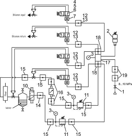
Fig. 6 Pneumatic diagram
Table 4. Composition of pneumatic system
|
No. |
Designation |
Name of item |
Qty |
Note |
| 1 |
S93000 |
Ball valve G 1/2″ |
1 |
|
| 2 |
PM11-NA |
Pressure relay |
1 |
|
| 3 |
MO43-P12 |
Manometer |
3 |
|
| 4 |
NA54N-15-02 IL |
Compressed air distributor |
4 |
|
| 5 |
A7E |
Coil |
4 |
|
| 6 |
122-800 |
Electric socket |
4 |
|
| 7 |
2931 |
Muffler |
8 |
|
| 8 |
PV 10/8 |
Blue PVC tube |
10м. |
|
| 9 |
MPL 10 |
Tube holder |
2 |
(2х10) |
| 10 |
W-3-1/4 2440 |
Manual pilot-operated valve |
1 |
«Festo» |
| 11 |
MC 238-ROO |
Pressure regulator |
2 |
|
| 12 |
1631 01 – 1/4 |
Hollow bolt |
3 |
|
| 13 |
1610 10/8 – 1/4 |
Bracket |
10 |
|
| 14 |
1493 10/8 – 1/4 |
Fitting |
1 |
|
| 15 |
1511 10/8 – 3/8 |
Fitting |
6 |
|
| 16 |
1631 03 – 1/4 |
Fitting |
2 |
|
| 17 |
UVspB–LA.00.23.000 |
Collector |
1 |
|
| 18 |
1631 03 – 1/4 |
Hollow bolt |
2 |
|
| 19 |
1410 10/8 – 1/2 |
Fitting |
2 |
Electric diagram is presented in Figure 7.

Figure 7 – Electric diagram: QF1 – three phase input autoswitch; SF1 – one phase autoswitch; TR – transformer; KM1 – KM4 – electromagnetic starters; KK1 – KK2 – thermal relays; Y1 – Y4 – electric valves; A1 – phase sequence control relay; A4 – А5 – controller; A2 – operating time counter relay; A3 – power supply unit 220VAC/24VDC; SB1 – emergency stop button; SA1 – SA2 – two way switch 0-1; PR1 – pressure relay; PS1 – pressure sensor; TR1 – TR2 – thermistors; K1 – K7 – electromagnetic relays; VD1 – VD10 – switch lights; HL1 – HL3 – front panel lamps; M1 – M2 – electric motors; TEH-О,TEH-W – tubular electric heater.
The design provides protection of power, motor, heater circuits and control circuits from short circuiting and protects the motors from overload by heat relays.
Power is supplied to the control device by automated input switch QF1 (see Figure 7).
The control circuit of the unit is protected by automated switch SF1 and separating transformer TR.
Motors М1, М2 and electric heaters are started by magnetic starters with heat protection, КМ1, КМ2, КМ3 and КМ4 respectively. Light indication of status and mode of operation of the unit’s components is displayed in the control device front panel.
A time counter relay A2 is installed for control of time operated.
Controller operation
The controller (figure 8) controls the process parameters (temperatures and pressures) and controls the unit’s operation in various modes.
The controller allows the operator access to unit control menu, which includes Settings menu (process parameter menu), alarm menu, emergency menu and process parameter viewing menu (temperatures and pressures).
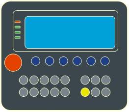
Figure 8 – General controller layout
The unit can be used in the following modes:
- manual with air;
- manual without air;
- automated with air;
- automated without air.